Sunday, July 20, 2014

FR Clothing

     In the electrical industry today, not enough can be said about safety.  Every day, whether on conference calls in the office or on tailgate discussions in the field, the inherent dangers of the electrical system are considered, mishap prevention is discussed and all incidents are evaluated to promote a safer working environment.  One particular, but very serious, danger when working near live conductors is the risk of arc flash.

     An arc flash, also called a flashover, is a rapid discharge of electrical energy across an insulating medium.  As the integrity of the medium begins to fail, a conductive plasma can form and reach a temperature of 36,000 degrees Fahrenheit, roughly the temperature of a particular surface layer of the sun.  This plasma is the fourth state of matter, ionized gas, and produces extreme heat and light, that are backed by the electrical energy of the system.  The propagation of heat from this plasma, in the form of plasma spray and infrared radiation, is what can cause substantial equipment damage and injury.  The available energy to feed this spectacle varies according to system fault duty, construction of electrical apparatus and fault clearing time.  Incident energy is what is received by the worker and it depends on the arc energy, the propagation directionality of the heat energy and the distance between the arc and the worker.  To protect the worker from the threat of arc flash, workers in the field are required to wear flame-resistant (FR) clothing, in compliance with OSHA regulations 1910.269.  The development of this type of clothing can be accredited to the work of Alice Stoll.

     In the late 1950's and early 60's, the United States Navy performed research on the effects of heat energy transfer to the human body's surface as part of its aerospace program.  Sailors would line up to volunteer to subject themselves to first degree burns in exchange for weekend passes at the Naval Air Development Center in Warminster, PA, near the Naval Air Station Joint Reserve Base Willow Grove. Headed by research physiologist Alice Stoll, this elaborate testing program lead to construction of a mathematical model, which related heat energy transfer to the body's surface as a function of three factors:  exposure time, level of heat and increase in temperature.  The term "second degree" burn was coined from these experiments as it was the point in burn severity, in which the epidermis would separate from the dermis.  This separation is what caused blisters to form.  Second degree was also the point at which human tissue could no longer dissipate heat by itself and was found to happen at an exposure to an incident energy level of 1.2 calories per centimeter squared, a level of heat energy that can be experienced if you were to hold the surface of your hand at the tip of a cigarette lighter flame for one second.  The mathematical model for human tissue was soon made relevant to other kinds of surfaces such as protective fabrics.  For the first time, any kind of fabric could be graded numerically on its effectiveness to withstand combustion.  Stoll clearly demonstrated that fabric constructed of inherently flame-resistant fibers was far superior to flame-retardant treated fabric.

     Today, regulation of FR clothing is a major portion of companies' electrical safety programs, mandated to have per NFPA 70E-2012, Standard for Electrical Safety in the Workplace.  FR protects the worker in that it will withstand combustion up to its rated heat energy value, will extinguish itself when the energy source is removed and will not melt.  These characteristics comply with OSHA's stipulation that clothing should not add to a worker's injury.  FR clothing will have the "FR" logo stitched onto it and is composed of natural fibers such as cotton.  Use of clothing that contain synthetic fibers, such as nylon and polyester, is forbidden as these fabrics have shown to continue to burn after the removal of incident energy.

     In the picture shown, a 100% cotton garment from Carhartt has a rated heat energy value of 8.8, also called an Arc Thermal Protective Value (ATPV).  This number means that the garment will withstand combustion when exposed up to and including 8.8 calories/centimeter squared of heat energy.  This doesn't mean that the garment will shield all the heat energy from underlying surfaces.  There is a 50% chance that the worker could receive a first or second degree burn.  Although this particular garment is cotton, only fibers that have been tested in the laboratory can be assigned an ATPV rating, as thickness, type of weave and color can play a role in flame resistant qualities.  The ATPV level required for use in certain applications is specified in a company's electrical safety program.  Met-Ed uses Hudson Workwear and Tyndale for its FR clothing.  An excellent blog on latest developments in arc flash safety is Electrical Arc Safety

     Article by Dan Scrobe III

Wednesday, July 16, 2014

Transformer Connections

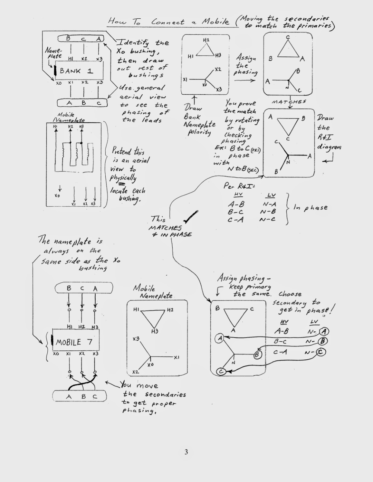
     Sometimes, transformers at substations need to be switched out for maintenance.  However, if there is only one transformer at a substation, a mobile transformer needs to be installed in parallel before the transformer is switched out.  The key to connecting a mobile transformer to the system lies in an understanding of the transformer nameplate.  

     The nameplate is typically drawn in an aerial view fashion in order to determine the physical location of the primary (H1, H2, H3) and secondary (X0, X1, X2, X3) bushing terminals, and it is typically located on the side of the transformer, as that of the X0 bushing, which is used for a neutral connection.  Since high voltage bushings will generally be larger than low voltage bushings, it is easy to identify the X0 bushing and nearby nameplate.  The vector diagram from the nameplate shows how the windings in the transformer are connected to each other and symbolizes the vector relationship of the three phases of electric connected to them.


     In Met-Ed, 69kV Delta transmission is used to source a distribution transformer, that provides power to a 13.2kV Wye distribution system.  Before switching out this transformer, it is important to visually trace out its connected conductors to phase markings outside of the area being disturbed, such as on a pole outside of the substation, in order to determine proper connections to the mobile transformer.  Met-Ed uses phase markings to indicate A-B-C phase rotation.  


     The picture shows primary leads entering the high side of the transformer called "Bank 1" in a B-C-A configuration to H1, H2 and H3 terminals respectively.  The vector diagram from its nameplate is drawn with its matched phase markings.  Since three phase power rotates counter-clockwise on the electric grid, visualize the vector diagram rotating counter-clockwise and you can confirm Met-Ed's A-B-C rotation.  If you visualize rotating the vector model on the nameplate of the mobile by 180 degrees, you will see that it matches up to that of Bank 1.  This check confirms that you have a compatable transformer.


     To connect the primary leads to the mobile, there are actually three ways to do it and still maintain A-B-C rotation.  In this example, for simplicity, it was chosen to connect the primary leads to the mobile transformer called "Mobile 7" in a B-C-A configuration to H1, H2 and H3 terminals respectively, to keep the same physical run of the conductors.


     To ensure that the secondary voltages of Mobile 7, once energized on the primary side, are in phase with the 13.2kV distribution system, secondary phase connections are chosen to ensure the in-phase relationship between primary and secondary vectors.  For example, it was chosen to connect secondary leads to Mobile 7 in B-C-A configuration to X1, X2 and X3 terminals respectively.  It can be seen from looking at Bank 1 that primary voltage vector A-B is in phase with secondary voltage vector N-A.  This can be proven also by looking at the mobile connections.  As long as both primary and secondary vectors are in the same geometric direction among both transformers, phasing will be successful.  Same visual check can be performed for the other phases.


     Article by Dan Scrobe III


Monday, July 14, 2014

Nikola Tesla

     If you ask any middle school student today who invented electricity, you are likely to get Benjamin Franklin or Thomas Edison as an answer.  If you ask who Nikola Tesla was, you are likely to get a puzzled look.  Many people don't realize that although Edison invented the light bulb, Tesla helped invent the means to effectively channel the electricity to power the light bulb.

     In the 1880's, Thomas Edison was using steam engines to generate and distribute 110 Volts of DC electric to power lights and motors in Manhattan.  DC (direct current) is an electrical circuit that has a constant voltage with current flowing in one direction.  The problem with this was that the location of the generator had to be within a few miles of where the power was being used, because power losses along the circuit caused significant voltage drops.  10 volts was an acceptable drop, therefore, the customer was receiving 100 volts.

     Nikola Tesla, an Austrian immigrant, arrived in New York City in 1884.  At the age of only 28, Nikola approached Thomas Edison with ideas that he had of electrical machines focusing on AC technology, that would help solve the problems at the time of power transmission and efficiency.  AC (alternating current) is an electrical circuit that has a varying voltage with current flowing in more than one direction.  Edison would not hear of AC and was interested only in ways to improve his DC distribution.

     Unlike Edison, Nikola Tesla was not a good businessman and lacked the necessary showmanship to promote his ideas.  However, a lecture that Tesla gave caught the eye of George Westinghouse, an industrial financier.  Tesla's contribution to the growing science of AC at the time was the invention of the polyphase induction motor, which could harness the cyclic energy produced by polyphase generators.  Among many others in the field, Tesla proposed how to transmit power over long distances without the power losses that was experienced on Edison's DC system.  To understand this, a quick lesson on electrical power is necessary.

     Power is the ability to do some kind work.  Electrical power is measured as the quantity of voltage and current.  A typical wall outlet in your house will provide 120 volts.  If a light bulb is connected and .5 amps is flowing through it, then the light bulb is utilizing 60 Watts (120 V * .5 A) of electrical power to keep it lit.  Typically, copper or aluminum have the ability to resist slightly the flow of current.  This resistance is a form of power consumption like the light bulb.  This power consumption is measured as the quantity of current squared and resistance.  Therefore, it would be more important to try reduce the current, rather than the resistance, to minimize power loss.  This is where Edison ran into trouble.  For him to reduce the resistance of his DC circuits, larger diameter of wire was necessary.  Of course, using more copper would only drive the cost up.

     Unlike DC, AC voltages can easily be converted from one magnitude to another through the use of the transformer.  A generator from a remote station could have its voltage stepped up to a very high magnitude to prepare for power flow along a transmission circuit.  Because of the power formula described above, a very high voltage would allow for a lower current.  As the transmission circuit got close to where the power was being used, the high voltage could be stepped down to a much lower voltage that would be safe for use.

     This clash of ideas over which technology was to be used to build the industrial might of the US as we know it became known as the War of the Currents.   As more people became aware of AC technology, Edison became very worried and went to the extreme of demonstrating the dangers of AC by performing public and gross electrocutions of animals.  When the State of New York mandated electrocution as a new method of capital punishment, it was rumored that Thomas Edison played a role in setting up the use of an old AC generator to provide the electric.  William Kemler was sentenced to death for murdering his wife.  He became the first person in US history to be electrocuted and is considered a casualty of the War of the Currents.

     In 1898, President Grover Cleveland flipped the switch to light the mass display of lighting at the World Fair in Chicago.  It was also known as the Columbian Exposition.  Westinghouse and Tesla won the rights to power the fair because they offered a bid that was half of the cost that Edison asked for.  This is where AC basically kicked off.

     Article by Dan Scrobe III