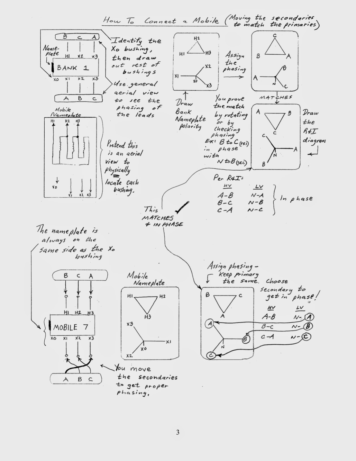
The nameplate is typically drawn in an aerial view fashion in order to determine the physical location of the primary (H1, H2, H3) and secondary (X0, X1, X2, X3) bushing terminals, and it is typically located on the side of the transformer, as that of the X0 bushing, which is used for a neutral connection. Since high voltage bushings will generally be larger than low voltage bushings, it is easy to identify the X0 bushing and nearby nameplate. The vector diagram from the nameplate shows how the windings in the transformer are connected to each other and symbolizes the vector relationship of the three phases of electric connected to them.
In Met-Ed, 69kV Delta transmission is used to source a distribution transformer, that provides power to a 13.2kV Wye distribution system. Before switching out this transformer, it is important to visually trace out its connected conductors to phase markings outside of the area being disturbed, such as on a pole outside of the substation, in order to determine proper connections to the mobile transformer. Met-Ed uses phase markings to indicate A-B-C phase rotation.
The picture shows primary leads entering the high side of the transformer called "Bank 1" in a B-C-A configuration to H1, H2 and H3 terminals respectively. The vector diagram from its nameplate is drawn with its matched phase markings. Since three phase power rotates counter-clockwise on the electric grid, visualize the vector diagram rotating counter-clockwise and you can confirm Met-Ed's A-B-C rotation. If you visualize rotating the vector model on the nameplate of the mobile by 180 degrees, you will see that it matches up to that of Bank 1. This check confirms that you have a compatable transformer.
To connect the primary leads to the mobile, there are actually three ways to do it and still maintain A-B-C rotation. In this example, for simplicity, it was chosen to connect the primary leads to the mobile transformer called "Mobile 7" in a B-C-A configuration to H1, H2 and H3 terminals respectively, to keep the same physical run of the conductors.
To ensure that the secondary voltages of Mobile 7, once energized on the primary side, are in phase with the 13.2kV distribution system, secondary phase connections are chosen to ensure the in-phase relationship between primary and secondary vectors. For example, it was chosen to connect secondary leads to Mobile 7 in B-C-A configuration to X1, X2 and X3 terminals respectively. It can be seen from looking at Bank 1 that primary voltage vector A-B is in phase with secondary voltage vector N-A. This can be proven also by looking at the mobile connections. As long as both primary and secondary vectors are in the same geometric direction among both transformers, phasing will be successful. Same visual check can be performed for the other phases.
Article by Dan Scrobe III
No comments:
Post a Comment